Friday 28 August 2015

Complete (kind of)

Sorry for the lack of posting over the last couple of weeks, I have been very busy trying to complete the bot for my deadline (today). The bot now works, although with a few small issues.

Robot with eyes, metal claw and bodywork
Since my last post, I have printed out both the bottom and middle sections in 100% infill in black, both of which came out at a very high quality. I also included mounts for some "eyes." These eyes were made using bits of brass piping with some LED's inserted in the middle. These look very effective and really help give the robot some character.
Also, the metal claws came back from the workshop and are of a really good quality and look very menacing.
Another thing I have completed is the bodywork. This has made using bits of scrap metal found in the workshop and bent into shape, then mounted using the designed mounting holes on the base section that I 3-d printed. This has worked well as it really allowed me to improvise with the body and make it look really beaten up and menacing!

However, in this time I have run into some pretty major issues with the electronics. I have been using an RC transmitter/receiver pair to control the motors and claw through an arduino.

The RC transmitter works by sending a PWM signal to the receiver. The nature of the PWM signal can be altered by programming the transmitter (e.g. which channel corresponds to which movement on the transmitter). This is because the primary idea of the receiver is to hook your servo's straight up to it. However, because I was using an arduino, I have had to read the PWM signal and then convert to my own varibale with defined range (e.g between 0 and 255 for the motor speed). This was easily done by using the pulseIn command.

When testing, I found that I could get the motors working and the claw working fine with the rc transmitter separately, however when combined many issues started occuring. The first one being that when using multiple PWM channels and the servo library, the servo librarys functions has some very strange and undesired effects on the PWM pins. This meant that when using the claw and the motors, the motors behaved very erratically (lots of jitter). This was a very hard problem to figure out but with the aid of Google I eventually got somewhere!

My next step was to write my own code for the servo, not using the library. I did this by writing the pin high and the pin low for a set amount of time using the digital write command. This worked fine when testing, however, it had power related issues to power as the Arduino froze when I moved the stick too quickly and it was powered by the battery (it worked fine with USB power).

I spent a long time trying to figure out the problem with no joy. With time running out there was only one immediate solution I could think of, using two arduinos. One for the motor control and one for the servo. When attempting this method, it didn't fully solve the power issue and it still freezes up occasionally. However, the motor drive arduino never freezes. So, when a freeze does occur, I have made a reset button on the transmitter using the motor drive arduino to reset the frozen one. Therefore, if the claws do freeze for some reason, a simple button press will sort out the problem.

Although not ideal, it works for the time being and I aim to sort out the problem at a later date.

Here are some photo's and video's of the house robot.


Thursday 20 August 2015

Small(ish) Problem

So while fiddling about with the claw, a wheel fell of! The connection bolt between the motor and the gear part of the bought in gear motor had been shaken loose. This normally would be a simple job of screwing it back in. However, because of the way I had glued the wheels on, I didn't have access to screw it tight again.

The wheel in question with the rim filed away
I had two options, either try and take the wheel of the motor or file away some of the rim to get access to the screw. I chose the latter because taking the wheel off has a high risk of shattering the rim and making it unusable.

After much filing with some needle files, I got access to the screw and re-inserted the wheel with gearbox to the motor.

Thursday 13 August 2015

The Claw

So this week my main objective was to get the claw mechanism working properly. With my servo having not arrived, I borrowed  another one for the time being with the same dimensions. I had to file the middle section a little but it fitted just fine.

I printed out the mechanism supports on the 3d printer, with 100% infill to make it strong and assembled it in the current bot. With the servo connected to the arduino, I figured out the maximum opening and closing points and wrote a quick program that opened and closed the arms.

This worked fine, although in my first attempt I accidentally soldered the ground pin of the servo to the reset pin on the arduino! However, at that time I was still working with the original MDF claw that I made for my first prototype. I decided that now was the time to try and make the new claw (which I designed a while ago) out of steel.

After a chat with a workshop staff member, I found the best way to do this would be to use the university's hot wire cutter. However, being the most used machine in the workshop, there is a long ( about one month) waiting list. This is completely fine however as the actual robot wars is not till December. I submitted the work order and 3d printed the claws so I would have something to show off for the time being. When the steel claws are ready, it would be a simple job of bolting them in place.

With these printed, and a servo with more torque installed, I had a completed claw mechanism. It seemed very strong. With some simple testing, I found it could easily lift a 500ml bottle of water, which equates to a weight of 500g. Seeing at antwieghts are 150g at most, I should easily have the grip to move them. Also, the newer design of the claw is much gripper and grab objects better than the other one.
Video of claw meachnism

Friday 7 August 2015

Some parts!

My motors arrived this week! This has meant I have been able to start putting some parts into place. Along with the wheels, I have no been able to start assembling the main part of the body. I went to the 3d printer and printed of a base part, now with mountings for the bodywork, and the newer simplified middle section.
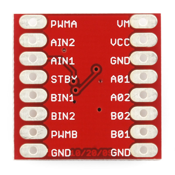
TB6612FNG motor driver

While they were printing, I started working on connecting the motor to the Arduino. I had bought a dual motor driver which was rated at a max current of 3.2A per channel. Seeing as each channel has a 2 motors with a stall current of 1.6A each, this was perfect for my application.

I noticed that with all the control pins on the left hand side, most of them were just digital inputs with two needing PWM. This meant that I could just solder it directly to the Arduino as there was a position that had PWM pins the right number of pins apart.

With this soldered on as so, and a program found off the internet, I downloaded it into the Arduino. It worked as planned, with the motors doing the movements as specified in the program.

Aruino with motor driver and 5V regulator
However, there was a problem. It would only work when powered with the USB cable and from the power supply, and not just from the power supply. This suggested I was powering it incorrectly. After much testing we realised this was not the case. The VCC (small signal supply voltage) on the motor driver was being powered by the Arduino's 5V source. However, we figured out that this source could not provide the necessary current to the chip for the motors to work (Arduino's  can provide 40mA at most).

Once figured out this was quite a simple fix and only involved powering VCC from the supply with a 5V regulator. When done the program would work correctly even when not plugged into the USB connection.

The next problem I have come across is how to attach the wheels to the motor. Because the wheels are Lego and the motors are not, they do not fit well. The motors have a notch in them so a good solution I thought was to make a Lego axle with a hole in it to fit the motor. I tried this but the 3d printer did not have enough accuracy to print it well enough. The next idea was to make my own rim. I designed it and printed it. However when done, although fitting the tyre well, the 3d printer could not print of the circle with a notch it well enough, meaning the motor could not fit on to it. After this, I then just chose to glue the wheels in place. Although not ideal this was the best way to do it and seems to be strong enough so far.

With this done I now have a robot that looks and drives like this: