Watch the video below to see all the battles!
Wednesday, 9 December 2015
Let Battle Commence!
The first robot wars which the house bot was invloved with took place on Saturday the 5th of December. It was a brilliant event and the house robot performed well! Thanks to the BEEES Committee for organizing such a great event.
Watch the video below to see all the battles!
Watch the video below to see all the battles!
Friday, 28 August 2015
Complete (kind of)
Sorry for the lack of posting over the last couple of weeks, I have been very busy trying to complete the bot for my deadline (today). The bot now works, although with a few small issues.
Since my last post, I have printed out both the bottom and middle sections in 100% infill in black, both of which came out at a very high quality. I also included mounts for some "eyes." These eyes were made using bits of brass piping with some LED's inserted in the middle. These look very effective and really help give the robot some character.
Also, the metal claws came back from the workshop and are of a really good quality and look very menacing.
Another thing I have completed is the bodywork. This has made using bits of scrap metal found in the workshop and bent into shape, then mounted using the designed mounting holes on the base section that I 3-d printed. This has worked well as it really allowed me to improvise with the body and make it look really beaten up and menacing!
However, in this time I have run into some pretty major issues with the electronics. I have been using an RC transmitter/receiver pair to control the motors and claw through an arduino.
The RC transmitter works by sending a PWM signal to the receiver. The nature of the PWM signal can be altered by programming the transmitter (e.g. which channel corresponds to which movement on the transmitter). This is because the primary idea of the receiver is to hook your servo's straight up to it. However, because I was using an arduino, I have had to read the PWM signal and then convert to my own varibale with defined range (e.g between 0 and 255 for the motor speed). This was easily done by using the pulseIn command.
When testing, I found that I could get the motors working and the claw working fine with the rc transmitter separately, however when combined many issues started occuring. The first one being that when using multiple PWM channels and the servo library, the servo librarys functions has some very strange and undesired effects on the PWM pins. This meant that when using the claw and the motors, the motors behaved very erratically (lots of jitter). This was a very hard problem to figure out but with the aid of Google I eventually got somewhere!
My next step was to write my own code for the servo, not using the library. I did this by writing the pin high and the pin low for a set amount of time using the digital write command. This worked fine when testing, however, it had power related issues to power as the Arduino froze when I moved the stick too quickly and it was powered by the battery (it worked fine with USB power).
I spent a long time trying to figure out the problem with no joy. With time running out there was only one immediate solution I could think of, using two arduinos. One for the motor control and one for the servo. When attempting this method, it didn't fully solve the power issue and it still freezes up occasionally. However, the motor drive arduino never freezes. So, when a freeze does occur, I have made a reset button on the transmitter using the motor drive arduino to reset the frozen one. Therefore, if the claws do freeze for some reason, a simple button press will sort out the problem.
Although not ideal, it works for the time being and I aim to sort out the problem at a later date.
Here are some photo's and video's of the house robot.


| Robot with eyes, metal claw and bodywork |
Also, the metal claws came back from the workshop and are of a really good quality and look very menacing.
Another thing I have completed is the bodywork. This has made using bits of scrap metal found in the workshop and bent into shape, then mounted using the designed mounting holes on the base section that I 3-d printed. This has worked well as it really allowed me to improvise with the body and make it look really beaten up and menacing!
However, in this time I have run into some pretty major issues with the electronics. I have been using an RC transmitter/receiver pair to control the motors and claw through an arduino.
The RC transmitter works by sending a PWM signal to the receiver. The nature of the PWM signal can be altered by programming the transmitter (e.g. which channel corresponds to which movement on the transmitter). This is because the primary idea of the receiver is to hook your servo's straight up to it. However, because I was using an arduino, I have had to read the PWM signal and then convert to my own varibale with defined range (e.g between 0 and 255 for the motor speed). This was easily done by using the pulseIn command.
When testing, I found that I could get the motors working and the claw working fine with the rc transmitter separately, however when combined many issues started occuring. The first one being that when using multiple PWM channels and the servo library, the servo librarys functions has some very strange and undesired effects on the PWM pins. This meant that when using the claw and the motors, the motors behaved very erratically (lots of jitter). This was a very hard problem to figure out but with the aid of Google I eventually got somewhere!
My next step was to write my own code for the servo, not using the library. I did this by writing the pin high and the pin low for a set amount of time using the digital write command. This worked fine when testing, however, it had power related issues to power as the Arduino froze when I moved the stick too quickly and it was powered by the battery (it worked fine with USB power).
I spent a long time trying to figure out the problem with no joy. With time running out there was only one immediate solution I could think of, using two arduinos. One for the motor control and one for the servo. When attempting this method, it didn't fully solve the power issue and it still freezes up occasionally. However, the motor drive arduino never freezes. So, when a freeze does occur, I have made a reset button on the transmitter using the motor drive arduino to reset the frozen one. Therefore, if the claws do freeze for some reason, a simple button press will sort out the problem.
Although not ideal, it works for the time being and I aim to sort out the problem at a later date.
Here are some photo's and video's of the house robot.


Thursday, 20 August 2015
Small(ish) Problem
So while fiddling about with the claw, a wheel fell of! The connection bolt between the motor and the gear part of the bought in gear motor had been shaken loose. This normally would be a simple job of screwing it back in. However, because of the way I had glued the wheels on, I didn't have access to screw it tight again.
I had two options, either try and take the wheel of the motor or file away some of the rim to get access to the screw. I chose the latter because taking the wheel off has a high risk of shattering the rim and making it unusable.
After much filing with some needle files, I got access to the screw and re-inserted the wheel with gearbox to the motor.
 |
| The wheel in question with the rim filed away |
After much filing with some needle files, I got access to the screw and re-inserted the wheel with gearbox to the motor.
Thursday, 13 August 2015
The Claw
So this week my main objective was to get the claw mechanism working properly. With my servo having not arrived, I borrowed another one for the time being with the same dimensions. I had to file the middle section a little but it fitted just fine.
I printed out the mechanism supports on the 3d printer, with 100% infill to make it strong and assembled it in the current bot. With the servo connected to the arduino, I figured out the maximum opening and closing points and wrote a quick program that opened and closed the arms.
This worked fine, although in my first attempt I accidentally soldered the ground pin of the servo to the reset pin on the arduino! However, at that time I was still working with the original MDF claw that I made for my first prototype. I decided that now was the time to try and make the new claw (which I designed a while ago) out of steel.
After a chat with a workshop staff member, I found the best way to do this would be to use the university's hot wire cutter. However, being the most used machine in the workshop, there is a long ( about one month) waiting list. This is completely fine however as the actual robot wars is not till December. I submitted the work order and 3d printed the claws so I would have something to show off for the time being. When the steel claws are ready, it would be a simple job of bolting them in place.
With these printed, and a servo with more torque installed, I had a completed claw mechanism. It seemed very strong. With some simple testing, I found it could easily lift a 500ml bottle of water, which equates to a weight of 500g. Seeing at antwieghts are 150g at most, I should easily have the grip to move them. Also, the newer design of the claw is much gripper and grab objects better than the other one.
Video of claw meachnism
Friday, 7 August 2015
Some parts!
My motors arrived this week! This has meant I have been able to start putting some parts into place. Along with the wheels, I have no been able to start assembling the main part of the body. I went to the 3d printer and printed of a base part, now with mountings for the bodywork, and the newer simplified middle section.
While they were printing, I started working on connecting the motor to the Arduino. I had bought a dual motor driver which was rated at a max current of 3.2A per channel. Seeing as each channel has a 2 motors with a stall current of 1.6A each, this was perfect for my application.
I noticed that with all the control pins on the left hand side, most of them were just digital inputs with two needing PWM. This meant that I could just solder it directly to the Arduino as there was a position that had PWM pins the right number of pins apart.
With this soldered on as so, and a program found off the internet, I downloaded it into the Arduino. It worked as planned, with the motors doing the movements as specified in the program.
However, there was a problem. It would only work when powered with the USB cable and from the power supply, and not just from the power supply. This suggested I was powering it incorrectly. After much testing we realised this was not the case. The VCC (small signal supply voltage) on the motor driver was being powered by the Arduino's 5V source. However, we figured out that this source could not provide the necessary current to the chip for the motors to work (Arduino's can provide 40mA at most).
Once figured out this was quite a simple fix and only involved powering VCC from the supply with a 5V regulator. When done the program would work correctly even when not plugged into the USB connection.
The next problem I have come across is how to attach the wheels to the motor. Because the wheels are Lego and the motors are not, they do not fit well. The motors have a notch in them so a good solution I thought was to make a Lego axle with a hole in it to fit the motor. I tried this but the 3d printer did not have enough accuracy to print it well enough. The next idea was to make my own rim. I designed it and printed it. However when done, although fitting the tyre well, the 3d printer could not print of the circle with a notch it well enough, meaning the motor could not fit on to it. After this, I then just chose to glue the wheels in place. Although not ideal this was the best way to do it and seems to be strong enough so far.
With this done I now have a robot that looks and drives like this:

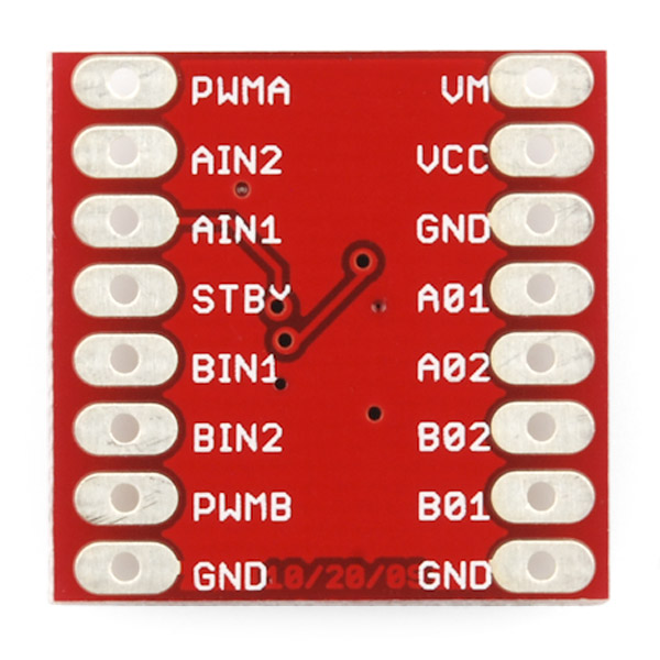 |
| TB6612FNG motor driver |
While they were printing, I started working on connecting the motor to the Arduino. I had bought a dual motor driver which was rated at a max current of 3.2A per channel. Seeing as each channel has a 2 motors with a stall current of 1.6A each, this was perfect for my application.
I noticed that with all the control pins on the left hand side, most of them were just digital inputs with two needing PWM. This meant that I could just solder it directly to the Arduino as there was a position that had PWM pins the right number of pins apart.
With this soldered on as so, and a program found off the internet, I downloaded it into the Arduino. It worked as planned, with the motors doing the movements as specified in the program.
 |
| Aruino with motor driver and 5V regulator |
Once figured out this was quite a simple fix and only involved powering VCC from the supply with a 5V regulator. When done the program would work correctly even when not plugged into the USB connection.
The next problem I have come across is how to attach the wheels to the motor. Because the wheels are Lego and the motors are not, they do not fit well. The motors have a notch in them so a good solution I thought was to make a Lego axle with a hole in it to fit the motor. I tried this but the 3d printer did not have enough accuracy to print it well enough. The next idea was to make my own rim. I designed it and printed it. However when done, although fitting the tyre well, the 3d printer could not print of the circle with a notch it well enough, meaning the motor could not fit on to it. After this, I then just chose to glue the wheels in place. Although not ideal this was the best way to do it and seems to be strong enough so far.
With this done I now have a robot that looks and drives like this:

Friday, 31 July 2015
Simplifying
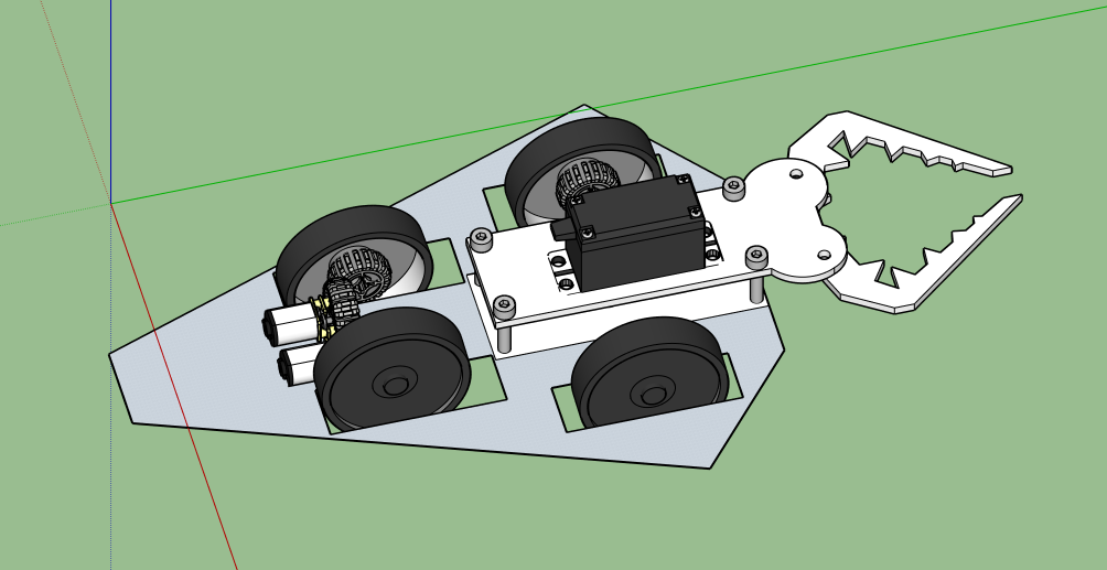
Parts have been taking much longer to arrive than expected so I have been having a look at my design and found a neat way to simplify it and remove two sets of bevel gears. This is because when I had been taking into account the size of the motors I had forgotten that most of the motor will be overhanging it's mounting position, meaning that in fact I could mount them in line with each other reducing the need for bevel gears.
This has also meant that I can reduce the length of the overall bot by about and inch, which has been quite needed as the length was starting to be too large, almost 9 inches. This would've meant that the bot could of taken up most of the arena.
Also, I have added mounts on the base for the bodywork to attach on to.
 |
| Newer simplified design |
Wednesday, 29 July 2015
Lego Bushes
 So after ordering all my Lego, I realised I had forgotten one main component, the lego bushings. These are used to keep axles in place. Because I only needed a couple and the minimum order spend on most brickowl stores is £2, I chose to try and 3d print them myself. As well as making a useful component, 3d printing something so small and precise would give me lots of experience in using the 3d printing process.
At first I downloaded a model from the 3d warehouse and adapted it so it could be printed easier (less overhanging edges). With this done I tried printing out my first model.
I found that this was too small. I went back to the design and started changing it by making the hole wider. After being printed out this also didn't fit. Then I had the idea of printing a row of the bushes but each one scaled up by a mm. I did that and found the one that gave me the best interference fit and the file.
With this success I now have the ability to print of as many lego bushings as I so desire. The final result is as shown below.

Monday, 27 July 2015
First Few Parts
A few parts have come thorugh! My lego bits and bobs have arrived from brickowl and the wheels arrived from eBay. The wheels seem really good and grippy which seems a relief as that is the one thing you cannot tell from a photo! I assembled the bits I had and found a couple of problems.
The first one being that the tolerances in the 3d printer and the recorded measurement of the wheel meant that there is a slight rubbing between the wheel and one of the parts of the printed middle section. This has been momentarily solved by filing away the offending part. However, I have also changed the 3d design so this won't be a problem again.
The next, slightly larger, problem I encountered was that the mounts for the rear wheels didn't seem strong enough and had a lot of play in them (meaning the wheel could move up and down). This is partly because I had to drill out the holes as I got the size wrong in the model. I have solved this by making the mounts larger. Also, the reason that it didn't seem strong I now realise is that when I was printing the middle section, to save time knowing that it was a prototype, I made the infill only 20%. This means that only 20% of the inside of the object is filled; and is surprisingly strong despite this. When I print the finial piece it will have a 100% infill which should make it much stronger
Friday, 24 July 2015
3d Printing
 So I've got a fairly decent design going on sketchup so I thought for my initial prototype I'd print of the middle section using the university's 3d printers. However, I did come across a problem. The 3d printer software requires a .stl type file. However, Sketchup has no export to stl option. This meant I had to go through the long winded process of exporting the file as a .dxf or .dwg to open it in autoCAD. However, when opened in autoCAD the export to .stl option failed. I found that this was true even for simple objects exported from sketchup such as a cube. This was a real problem as it meant I would then have to design my entire again on autoCAD. Although not the end of the world this would really slow down my progress.
After much fiddling about with the two software packages, I found a solution. Google Sketchup, as well as a 3d warehouse, also has an extension warehouse where you can download add-ons for sketchup made by other people or companies. A quick search revealed there was an extension for importing and exporting .stl files. I tried it out and found it worked fine!
I went to the workshop, shown how to operate the printer and then printed out the middle section! It took a couple of hours but when done added the mdf claws to see how to fit it together. The end result is shown below.

Thursday, 23 July 2015
Designing away
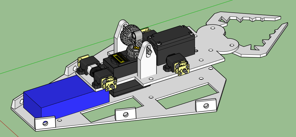
Parts are taking a while to arrive so I am taking this time to make my design as good as possible. It seems everytime I go back to look at the design I find something slightly wrong with it, for example some of the mounting points were at different heights meaning that the bevel gears would not mesh correctly. This is stuff that is not immediately obvious but would be when assembling the bot. I am hoping out to iron out as many problems at this stage as possible before assembling the design.


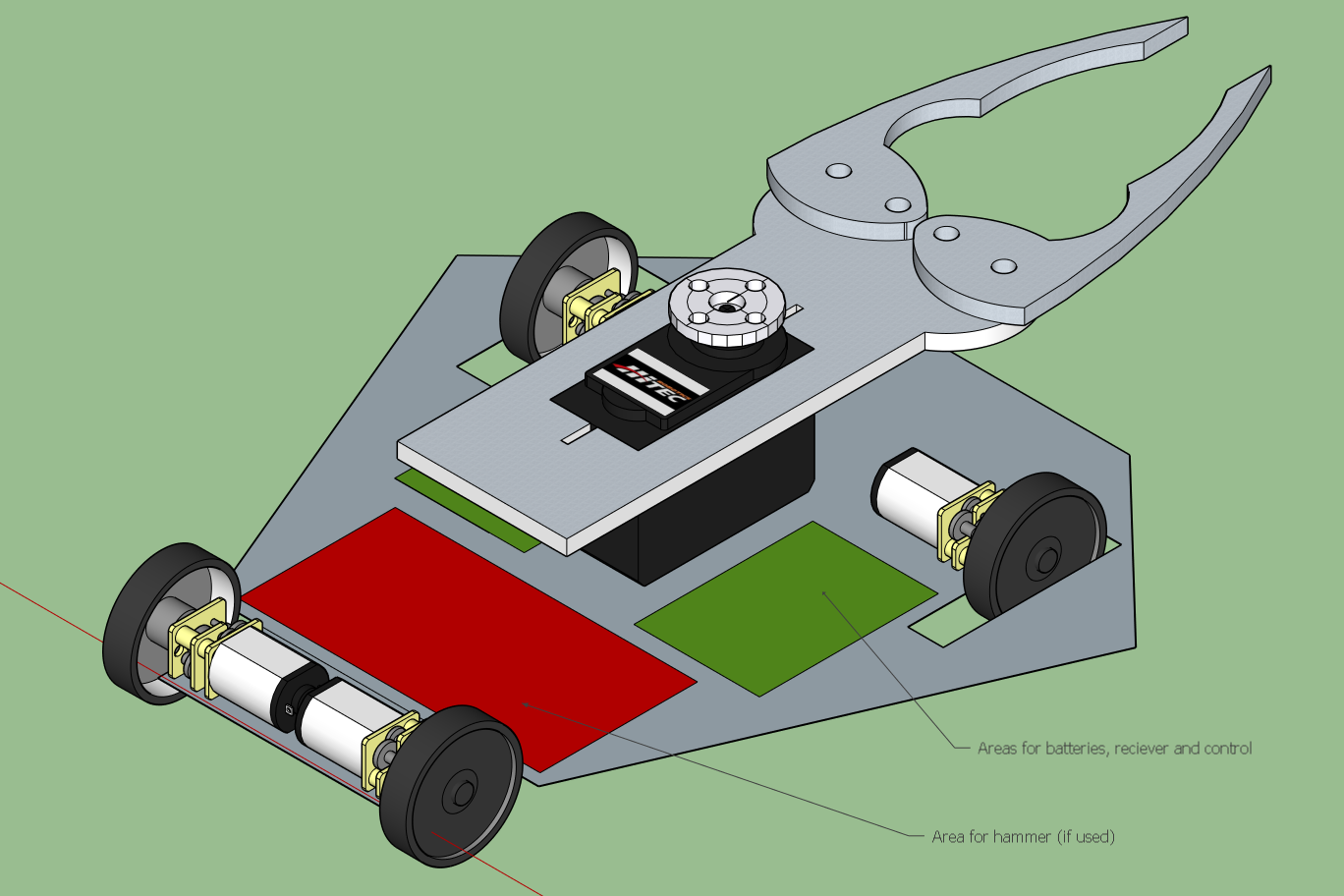
As you can see, bevel gears are being used everywhere to help keep the narrow scorpion shape. The hammer is on a sliding mount meaning I can adjust it to make sure the gears mesh well (The blue section represents the battery).
Wednesday, 22 July 2015
Lego!
So a couple of days after I ordered my lego wheels I discovered a website called brickowl. It enables you to buy cheap specific lego parts off different stores. I found this very useful as I can now order the bevel gears for a low price, something that was looking to be very expensive on site such as eBay. I've ordered a few different parts to test out hopefully they should be ok

Monday, 20 July 2015
More Designs
With parts ordered and knowing their dimensions from data sheets, I am now in the process of designing the complete model on Google Sketchup. I have been having a few issues with fitting the motors in sideways as it has been making the robot too wide if I wanted to keep the same kind of shape (wide at the front then getting narrower). I was then told about bevel gears. These transmit rotary motion 90 degrees. This has meant I can place my rear motors in line with the front of the robot and help keep it thinner. The bevel gears I have used lego gears for ease, although these can be changed to metal at a later date
The claw has also been redesigned to be more scorpion like and scarier.

The claw has also been redesigned to be more scorpion like and scarier.
Saturday, 18 July 2015
The Hammer
The hammer component has been a real stumbling block on the design of the robot. The aim was to design a hammer that, most importantly, looks really cool and works well. I had two options, I could either use a pneumatic ram or a motorised system.
To start off with I looked at using a pneumatic ram. I found this post on a forum about a very successful antweight robot. The author mentions in the alternative parts section that lego pneumatics could be used for the ram. I started researching the lego and came across some interesting things.
For a lego pnuematic system you need these following items:
To start off with I looked at using a pneumatic ram. I found this post on a forum about a very successful antweight robot. The author mentions in the alternative parts section that lego pneumatics could be used for the ram. I started researching the lego and came across some interesting things.
| Lego Ram |
For a lego pnuematic system you need these following items:
- Ram
- Valve
- Air Tank
- Pump
I found a kit for all of these things for £50 here. However, extra parts would have to be purchased as the lego does not support electrical switching (all done by hand). This would mean an electric vacuum pump and solenoid valve would have to be found that interfaces with the lego parts. This would look like the below design if made:


Another, much simpler way, to make the hammer would be to use some kind of motor, such as a stepper motor or a servo.
After much thought, I chose to use a servo. This is because, despite the fact that the pneumatic stuff would be cool, it would be way too complicated. Also, the power given by the pneumatic ram would be over the top as I don't really want to cause too much damage to the other robots. However, the pneumatic stuff could be added in if a second version of this bot was ever made.
Thursday, 16 July 2015
Parts
So I ordered most the parts I need a couple of days ago and I thought I'd list what they are.
 Motors
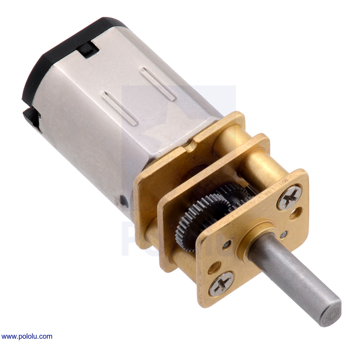
I have ordered 4 of these micrometal gearmotors. I have chosen the gear ratio to be 100:1. This is slightly slower than most other antweights but has much more torque (320rpm with no load and 2.2kg-cm at stall). This is what is needed for a house robot. Using the specs given, this gear ratio would give a speed of about 2mph with a wheel size ratio on 1".
I also got a standard motor mount for each motor.
 Wheels
Wheels were a surprisingly tricky part to find. I needed four small and grippy wheels. I started looking at the pololu wheels but found they were often too large. Eventually I stumbled across lego wheels. I seemed to be able to find the correct size of wheels but I had no way of telling how grippy they were from the photos. Eventually I took the plunge and ordered 4 wheels intended for a crane kit from eBay. They had a 60mm diameter and a 20mm width.
Battery
.jpg) I needed a large battery, much larger than any of the other antweights. This is because, not only does it have more "stuff," it also has to fight in every single round of the robot wars. A quick bit of research found that the best type of batteries to use would be the lithium polymer (Lipoly) type of battery. These batteries have a very high capacity to weight ratio and are the go to battery for RC enthusiasts. The one I chose, here, has a very large capacity but still fairly small so should be able to fit in well inside the robot.
I needed a large battery, much larger than any of the other antweights. This is because, not only does it have more "stuff," it also has to fight in every single round of the robot wars. A quick bit of research found that the best type of batteries to use would be the lithium polymer (Lipoly) type of battery. These batteries have a very high capacity to weight ratio and are the go to battery for RC enthusiasts. The one I chose, here, has a very large capacity but still fairly small so should be able to fit in well inside the robot.
Servo
For the servo used to control the claw, it was important that I chose a servo with a very high torque. This is so that it could easily pick up other bots. There is also no need for it to be super past either. At first I started looked at retract servos. These are servos traditionally used for landing gear on RC aircraft so they can only hold two positions which are 180 degrees apart. Because of this it is possible to make them with lots and lots of torque. However, if I were to use a retract servo it would mean that I would have to design my mechanism perfectly with no room for error and also it could only be open and close, with no position in the middle. With that in mind I had to find just a normal, but high torque servo.
Eventually I found a good servo that gave me 11kg-cm. This is much higher than any others at this price (just under £10) as often to get a really high torque servo you can pay upwards of £30-40.
MotorsI have ordered 4 of these micrometal gearmotors. I have chosen the gear ratio to be 100:1. This is slightly slower than most other antweights but has much more torque (320rpm with no load and 2.2kg-cm at stall). This is what is needed for a house robot. Using the specs given, this gear ratio would give a speed of about 2mph with a wheel size ratio on 1".
I also got a standard motor mount for each motor.
WheelsWheels were a surprisingly tricky part to find. I needed four small and grippy wheels. I started looking at the pololu wheels but found they were often too large. Eventually I stumbled across lego wheels. I seemed to be able to find the correct size of wheels but I had no way of telling how grippy they were from the photos. Eventually I took the plunge and ordered 4 wheels intended for a crane kit from eBay. They had a 60mm diameter and a 20mm width.
Battery
Servo
For the servo used to control the claw, it was important that I chose a servo with a very high torque. This is so that it could easily pick up other bots. There is also no need for it to be super past either. At first I started looked at retract servos. These are servos traditionally used for landing gear on RC aircraft so they can only hold two positions which are 180 degrees apart. Because of this it is possible to make them with lots and lots of torque. However, if I were to use a retract servo it would mean that I would have to design my mechanism perfectly with no room for error and also it could only be open and close, with no position in the middle. With that in mind I had to find just a normal, but high torque servo.
Eventually I found a good servo that gave me 11kg-cm. This is much higher than any others at this price (just under £10) as often to get a really high torque servo you can pay upwards of £30-40.
Wednesday, 15 July 2015
Initial Designs
With the claw design sorted, I can now move on to thinking about how the whole thing is going to fit together. Then parts could be chosen and ordered. The very first thing that was decided upon would be that the house robot would be 4 wheel drive. Because of the weight limit, most antweights can only have 2wd. However, because I don't have a weight limit it would be a good idea to have 4wd as I would have more grip meaning I could easily move other robots without them moving me.
Speaking to previous years competitors and looking at bots from the antweight world series, I was shown to a range of micrometal gearmotors which could give out a very high amount of torque for the size of the motors. I decided to use one of these motors however the exact gear ratio would be decided upon later.
With this in mind, I made my first design on Sketchup. Google Sketchup conveniently has a 3-d warehouse where you can download models made by other people. These are often to scale so really helped save time when making this initial design. Both a servo and the gearmotors had been modelled before by other people so I could download them and add them to the design.
With that in mind I had my first initial design:
 After I made this I showed it to a few of the previous years competitors and they gave me some feedback including enclosing the wheels so they are armoured for enemy bots and flipping the claw upside down to be able to get a better grip on enemy robots and also because it looks cooler.
This lead me on to my next design, which also incorporates a pneumatic hammer, which I will discuss in my next blog post.
 |
| Pololu gearmotor |
Speaking to previous years competitors and looking at bots from the antweight world series, I was shown to a range of micrometal gearmotors which could give out a very high amount of torque for the size of the motors. I decided to use one of these motors however the exact gear ratio would be decided upon later.
With this in mind, I made my first design on Sketchup. Google Sketchup conveniently has a 3-d warehouse where you can download models made by other people. These are often to scale so really helped save time when making this initial design. Both a servo and the gearmotors had been modelled before by other people so I could download them and add them to the design.
With that in mind I had my first initial design:
This lead me on to my next design, which also incorporates a pneumatic hammer, which I will discuss in my next blog post.
Monday, 13 July 2015
The Claw
 The first part I decided to focus on was the claw mechanism. After some quick research I found a claw that I could buy that was servo operated and looked really cool! However, I quickly realised that this would not be a good choice as it could only open to just under 4". Seeing as most the robots are 4" wide, it would mean that the claw would struggle to pick any of them up. However, I liked the metallic look of it and the fact it was controlled by a servo and decided that any claw I had needed to be metal (plastic would be easily broken by spinners) and controlled by a servo.
 I am somewhat of a novice when it comes to CAD, having only really used a tiny bit of SolidWorks before for a GCSE project a few years ago. With the software installed on the university computers I had two choices, AutoCAD or Google Sketchup. I started of by having a bit of a play with AutoCAD, knowing that it is a very useful and powerful tool in the right hands. However, in my hands I found it difficult to make even the simplest of shapes and I could see myself spending a very long time learning how to use the package. I decided that, because all my shapes are fairly simple, to use Google Sketchup, safe in the knowledge that if anything I needed to do that required a more complex tool I could export from Sketchup to AutoCAD.
After a while of playing about on Sketchup, a fair few mistakes and start overs, I had my first claw design. This, I hoped, would work just like the above claw but I now had the ability to make it out of whatever material I so desired. I chose at first to print it out on the laser cutter in MDF to check the mechanism was working properly.
This being my first time using a laser cutter it took a couple of attempts to get it right (my first attempt ended up with a miniature claw!) but eventually I had it printed out fine. I assembled it (as shown below) and surprisingly, everything worked fine! The claw now opens to about 5.2" and can now be made out of whatever material I want.

Tuesday, 7 July 2015
So it begins...
My project this summer entails building a house robot for the University of Bristol's Robot Wars. This, much like the original TV show, which we all know and love, involves pitting two robots against each other until one robot is either immobilised or thrown out of the arena.
However, this robot is to compete in the antweight series of Robot Wars. There are a few differences between the antweight series and the televised one (heavyweight). The main one being (obviously) the weight. Heavyweight robots have a weight limit of 100kg whereas the antweights have a limit of only 150g and have to be able to fit into a 4" cube. Also, antweight robot arenas have two sides with no barriers for the robots to be pushed off.
This video shows the last robot wars at Bristol.
From this you can see what kind of robot I am aiming to build. However, there is one main difference between my robot and all the others. Mine is going to be a house robot.
A house robot is an obstacle in the main arena that takes part in every single battle. House robot's are bigger (no weight or size limit) but are restricted to certain zones and only take part in the action when a players robot enters that zone and once the player leaves that zone, it cannot chase.
House robots are an important part in the robot wars TV series success. They provided a recurring character that the audience could latch on to and would still be there if a popular competitor was knocked out at an early stage.With that in mind, it is important that the whole design of the house robot is to look seriously "cool" and threatening. All the other robots in the original series have "characters" to play and were all very unique so it would be best if I decided on a theme to go with first.
After talking to some of the previous years competitors for inspiration, it was decided that I would make a scorpion type robot with claws and a hammer. The idea being that it would not destroy robots, only pick them up and move them to break up the play, and with a hammer that looks really cool but doesn't do loads of damage With this decided the next stage would be to start designing an initial model on CAD and choosing parts.
However, this robot is to compete in the antweight series of Robot Wars. There are a few differences between the antweight series and the televised one (heavyweight). The main one being (obviously) the weight. Heavyweight robots have a weight limit of 100kg whereas the antweights have a limit of only 150g and have to be able to fit into a 4" cube. Also, antweight robot arenas have two sides with no barriers for the robots to be pushed off.
This video shows the last robot wars at Bristol.
A house robot is an obstacle in the main arena that takes part in every single battle. House robot's are bigger (no weight or size limit) but are restricted to certain zones and only take part in the action when a players robot enters that zone and once the player leaves that zone, it cannot chase.
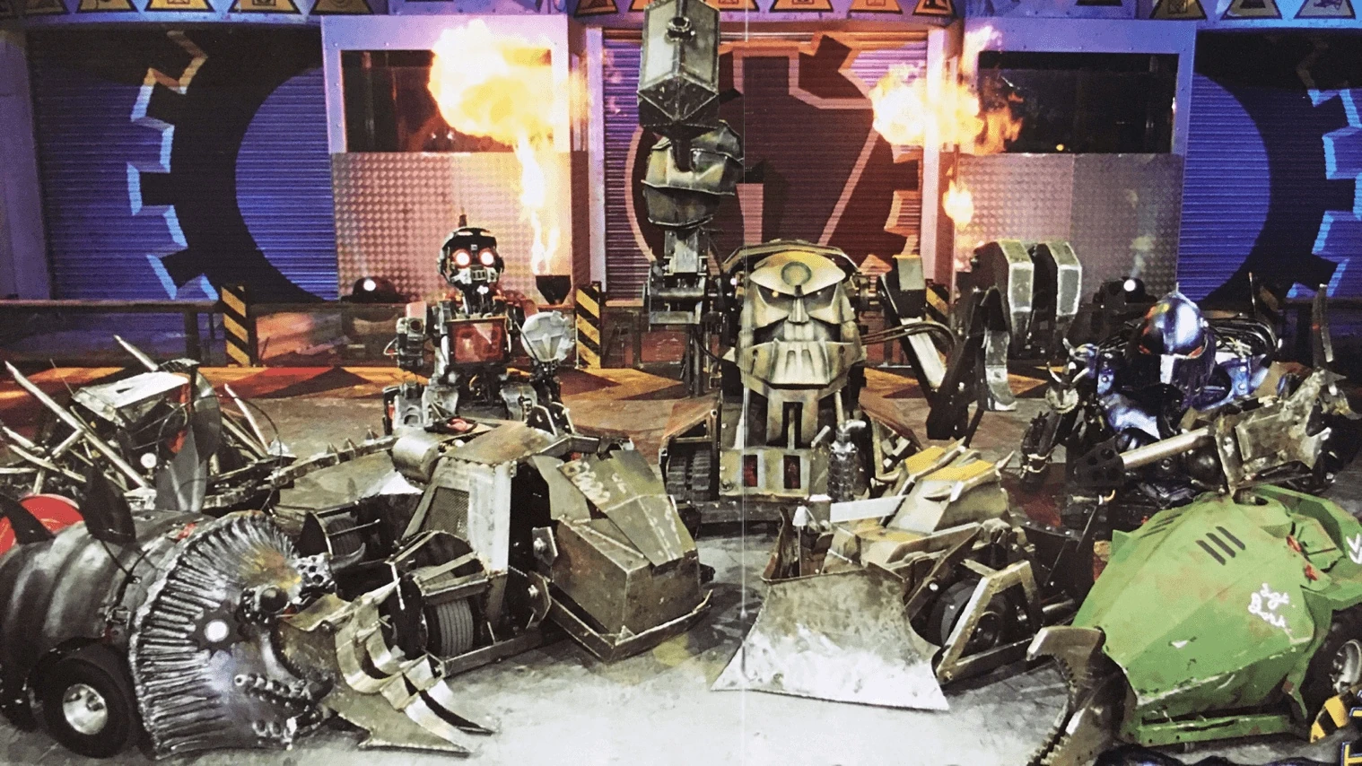 |
| House Robot's for the original Robot Wars TV series |
After talking to some of the previous years competitors for inspiration, it was decided that I would make a scorpion type robot with claws and a hammer. The idea being that it would not destroy robots, only pick them up and move them to break up the play, and with a hammer that looks really cool but doesn't do loads of damage With this decided the next stage would be to start designing an initial model on CAD and choosing parts.
Subscribe to:
Posts (Atom)